
V2 Marine Design - an Orca3D Marine CFD Success Story
The High Performance Sterk 31 benefits from CFD analysis

The integration of Computation Fluid Dynamics (CFD) into the small design office has been an evolutionary process that has now reached a significant tipping point – in a good way. Traditionally CFD has been expensive, time consuming, and required both specialized equipment and experienced operators. Software like Orca3D Marine CFD, as described here, has removed many of the barriers for solo designers evaluating the performance of new designs or refining existing designs within their own office.
Sasha Vlad runs V2 Marine Design in Latvia. He has not been static in either his place of residence nor his design technology. Born in Romania, he has lived, studied and worked in South Africa, New Zealand, England, and now has his design office in Latvia. A variety of experience as well as geography has also given him a good perspective on the process of design and construction. New Zealand taught him traditional wooden boatbuilding, while Southampton, UK earned him a degree in Naval Architecture. Southern Wind Yachts provided a 5-year stint in the world of large luxury yachts and KND Naval in South Africa gave some experience in high grade military specifications for high-speed metal boats. All to say that each experience added to Vlad’s treasure chest of knowledge.
When quizzed about his choice of sail or power as a design focus, he admits that initially it wasn’t obvious. He has a love of sailing and his schooling in Southampton had a heavy bias towards sail (an experience that he would recommend to anyone interested in the field). But when he did some serious thinking about designing on his own and of the two possible markets, he felt the power boat world bigger and offered more opportunities and therefore had the greater potential for work.
The Need for CFD

A view from below of a 60 knot CFD run. The purple areas are wet, the blue is dry and the intermediate colours are a mixture of air and water. The benefit of the steps in removing wetted area from the hull is evident.
His first projects were low risk, as he puts it – somewhat evolutionary in hull shape, a moderate to deep vee hull with no steps. During those projects he felt confident that the performance and behaviour would be predictable, and they turned out well. It was his first boat for Canelli Yachts, a 30-footer, that led to his turning to CFD for help. The design brief was for a stunning boat that was fast and behaved well, with both the hull shape and interior left unrestricted – the kind of design brief that all designers would like to receive. However, to get the performance from a mid-weight production boat Vlad felt steps were necessary and for those he needed some technical help. (see side bar on CFD at the end of this article)
A call to Bruce Hays at Orca3D and an Orca3D Marine CFD trial licence introduced him to the technology, and after setting up his company finances, his first license was underway. In order to run the Orca3D Marine CFD efficiently an upgraded computer is recommended, although not required. Vlad calls his desktop computer “not that fancy,” but in most people’s terms it would be an enviable setup. He uses a 12 core AMD Ryzen 9 5900X processor with 64GB of RAM (AMD’s latest Threadripper Pro CPUs offer even more power at a very reasonable cost). The files created during a run are significant, especially if animations of the planing attitude are desired. To handle this, he has 7 terabytes of local SSD storage and then sends the whole folder up to the cloud to clear his office computer after the project is complete.
The CFD process creates a region, or domain, that extends beyond the hull forward and aft, above and below, and to port and starboard. This domain is divided into discrete 3D cells in order to assess the fluid's behavior (water, air, or a mixture) as it flows from one cell to the next. The fineness of the mesh of cells affects the accuracy of the results. There might be from 2 to 30 million cells in a mesh. Vlad uses about 20 million cells for his hulls which leads to a 14-hour run for one speed for one of his power boats. So that is an overnight run with analysis in the morning while you start the next run. That may seem like a long time per run, but he firmly believes that a few more days of CFD analysis at the design stage is much better than a few weeks in the shop modifying a hull that is not quite right. The price of a few more days in virtual testing is a fraction of the cost of shop floor reworks.

The CFD mesh detail on the strakes and aft end of the step. The automatically defined mesh parameters are one of the time saving features of Orca3D Marine CFD.
In Vlad’s design process he focuses on the surface below the water, while long time business partner Carlos Vidal (each operating their businesses independently) takes care of the topside visuals, the deck and interior. The combination of talents lets Vlad concentrate on the handling and performance while Vidal is all about aesthetics and function.
Vlad used to design with less reliance on science and more on experience and feel, but now he finds the CFD analysis lets him develop new shapes with confidence. In the past the process was very much evolutionary – one step at a time with each new design. By necessity the advancement with each successive design was small, since there was risk in making a large change without some science as backup. With CFD analysis now available to prove the design in the computer, he is able to make significant advances with confidence. The Sterk 31 is a case in point.
His first boat with ventilated steps was the project that justified the purchasing of Orca3D Marine CFD. There are various flexible licensing/price options which you can review at Orca3d.com.

A Rhino3D rendering of the inverted hull shows the step and strake configuration.
Steps are not simple notches in the bottom of the hull - to do them well requires considered experimentation, either physical or with CFD. The goal of a stepped hull is to reduce drag and define the running attitude of the boat when on plane. The planing attitude at speed is controlled by the relative positioning of the steps – their height determines (which determines the amount of ventilation), their angle of incidence of the planing surface vs trim angle of the craft, and their fore and aft position all play a role in how the boat rides. The steps are not perpendicular to centreline, but rather in the shape of an arc going forward. This design feature allows ventilation even in turns and keeps the centre of buoyancy longitudinally close to original upright position, thus ensuring safe and predictable handling. With a double step, Vlad likes the center of gravity of the loaded boat to be close to the second step as this is the natural pivot point of a stepped hull.
The CFD run, which he sets up as though the boat were towed with a rope from the center of gravity, starts with the boat at rest and then accelerates the boat up to speed. A significant difference with Orca3D Marine CFD compared to other CFD packages is its template architecture and integration into Rhino3D. The templates provide the appropriate settings for the meshing of the hull, step size, and run duration based simply on choices of a coarse, normal, fine, or extra fine grid. If more detailed control over settings is desired it is possible but, in most cases, one of the pre-defined levels is suitable. This means the designer does not have to be a CFD expert, simply a sensible interpreter of the results. The integration into Rhino3D also means, other than ensuring the boat is a complete solid, there is no converting of CAD formats or special flotation conditions. Orca3D Marine CFD is launched straight from Rhino3D.

The Sterk 31 at 30 knots; magenta areas are fully wetted, blue are fully dry
The resulting model behaviour is much as you would see on the water. The bow rises as the boat gains speed, reaches a maximum as the hull goes “over the hump” and then begins to level out, finally reaching a planing trim attitude. With transverse steps added to the running surface of the hull Vlad’s computer runs showed that the initial power required to get the boat up on a plane and “over the hump” was greater with steps, not less. This is due to negative pressure behind the step (suction) at slow speeds. However, the gain with steps is two-fold - once up on plane drag is reduced when compared to a traditional deep-vee hull while top speed increases for the same amount of power installed (he is designing in the 50-60 knots range) and the running attitude is nicely controlled by the angle of the steps.

CFD accurately predicts the running attitude of the boat.
An image at 30 knots (above) and 60 knots (below)

Initial runs are done with a clean vee hull with no strakes, as his base condition. Then strakes are added to provide extra lift and also to deflect the water from the hull. Although trial and error may seem like an ‘old-school’ approach, when done in the computer it all makes sense. It is still the human who provides the ideas and the CFD that gives the score. The report card’s measure of success is reduced drag, steady trim angle and a spray pattern that keeps the deflected water away from the hull and passengers. Rather than trials on the water, the design office experimentation is precise and rewarding and the flow streamlines and spray patterns are something that one cannot, in any practical way, determine on the water. It just can’t be done without an underwater camera viewing a tufted hull or hot wire flow instrumentation. With computer flow visualization, struts or strakes can be placed to intersect or control the flow as desired.
In the case of Vlad’s stepped hull, decisions that were aided by the CFD drag measurements were:
- moving the aft end of the lifting strakes to the step location to reduce drag
- adjusting the height of the steps (conservative by his definition) to keep enough of the hull wetted to result in good ‘bite’

A novel detail refined by CFD is the rail on the outer edge of the strakes. It deflects the spray along the axis of the lifting strake giving fantastic directional stability and eliminating spin-out.
Not only does the CFD analysis let you move ahead with confidence, it allows one to guide the customer, when required, with similar confidence and justification. The client may have a grand plan for super sonic speeds or a seven-stepped hull but their ideas are more dreams than well-founded thoughts. It is much easier to pare back ideas to a successful approach when backed up by science and images. A single animated CFD run of a very bow-up boat is a powerful illustration to persuade a customer that maybe that huge step up forward is not the right answer.
Vlad points out that running attitude is one of the prime uses he has for CFD. The decision on the planing trim of a boat is one of aesthetics and efficiency. By adjusting planing surfaces, steps and center of gravity the bow up attitude can be set for the boat. And with a stepped hull, that trim is somewhat immune to trim tabs and center of gravity. That means if you adjust the running trim at the design stage, there is little need for tabs on the boat – in fact they have eliminated the tabs from the Sterk 31. A critical safety consideration is the prevention of undesirable handling like porpoising and chine walking. Both of these characteristics can be eliminated in the design phase through CFD, instilling client confidence and assuring the design investment.
In other projects ultimate speed is not the goal. Some designs are slow speed cruisers where hull efficiency improvements and streamlined appendages result in lower running costs and lower co2 emissions. With CFD Vlad is able to quantify the reduction in drag from design iterations and choose a hull that is optimized to the craft’s operation envelope. A European client selling hundreds of inland waterway boats put the design brief as “Lower fuel consumption gets more sales.” This goal can only be achieved with tools like Orca3D Marine CFD.

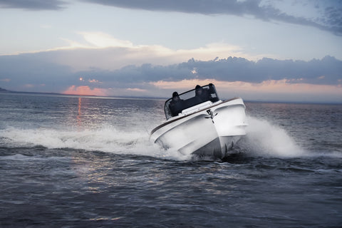
Above is the Sterk 31 CFD planing-run in calm water and below the real life image in choppy seas. Excellent correlation.

“It has given me the confidence to design my first stepped hull and go straight into production.”
It isn’t always about speed; sometimes it is about trim attitude or spray control. In a recent project a client asked him to help with water spraying onto an aft swim platform at planing speeds. It wasn’t a simple problem of weight and trim, but high-pressure water finding its way though shut lines and hinge recesses on bulwark doors. Step one was to recreate the problem in CFD and, sure enough, he could demonstrate that at running attitude and speed, water will indeed spray onto the swim platform. The thought process is still a human one, in this case modeling new channels to relieve the pressure and re-route the flow, but CFD was the proof without relying on expensive trial and error on the water.
Was the Orca software a necessity for his latest projects? “Absolutely.” That is a strong vote for CFD. It provides new insights into the “why,” not just the “how much” of marine design and new hull shapes are being developed with confidence.
Sasha Vlad – V2 Marine Design – V2marine.com
Orca3D Marine CFD – Orca3D.com
____________________________________________
CFD Side Bar
CFD (Computational Fluid Dynamics) is the assessment of fluid flow using computer numerical analysis. In its early days, perhaps 1950 through 1990, tank testing, even with its scale-effect flaws, was the standard for predicting the wave-making and frictional drag of marine vessels. Whether it was naval ships or America’s Cup boats, tanks from 100 to 3000 feet long with sophisticated towing dynamometers and operators with years of experience were used to assess performance. But it was time consuming and expensive. The fabrication of a model, often in the 20-foot range, the ballasting to operational displacement, and then a series of runs to cover the range of expected speeds was limiting to most designers. Other options to assess the performance of hulls were needed and computational fluid dynamics (CFD) was one of those options.
Early development of CFD routines did their best to match the accuracy of tank testing, but confidence in results was slow to build. And with early computers’ slow processors, the time to perform a run was prohibitive. Over the years Orca3D Marine CFD’s computer code efficiency, accuracy, and ease of operation have made a major leap and the computers themselves are now affordable for the average design office. Having CFD capability within a small design office was unheard of ten years ago and now it is becoming commonplace.